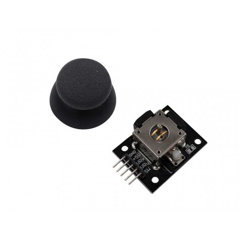
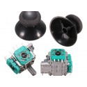
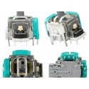
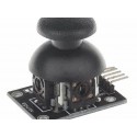
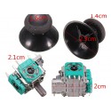
This is Joy Stick Module PS2 Breakout Sensor very similar to the ‘analog’ joysticks on PS2 (PlayStation 2) controllers. Directional movements are simply two potentiates – one for each axis. Pots are ~10k each. This joystick also has a select button that is actuated when the joystick is press down.
With the help of this Joystick Module, you can measure position coordinates on the X and Y axis by moving the “hat”. It also contains a switch that is press-able by pushing the “hat”.It also contains a switch that is press-able by pushing the “hat” down. Similar to the XBOX controller.
The X and Y axes are two 10k potentiates which control 2D movement by generating analog signals. When the module is in working mode, it will output two analog values, representing two directions. This module uses the 5V power supply, and value, when reading through analog input, would be about 2.5V, a value will increase with joystick movement and will go up till maximum 5V; the value will decrease when the joystick is moved in other direction till 0V.
Applications:
-As square wave signal generator which generates a square wave signal
-To provide a signal to the stepping motor driver
-Adjustable pulse generation for chip use
-Produce variable pulse signal, the control-related circuit (PWM dimming, speed)
Module Description:
Frequency is divided into three ranges:
-XXX (no decimal point):the smallest unit is 1Hz,the range 1Hz-999Hz
-XX.X (decimal point in ten): The minimum unit is 0.1Khz; the range of 0.1KHz-99.9KHz
-X.X.X.(there is three decimal point): the smallest unit is 1Khz; the range 1KHz-150KHz
Frequency Display Example:-100 indicates that the PWM output pulse of 100Hz
- 54.1 indicates that the PWM output pulse of 54.1KHz
- 1.2.4 Indicates that the PWM pulse output 124KHz
- Duty Cycle in the range:0 to 100
- Three frequencies duty cycle is the same, all the parameters non-volatile
Features:
-2.54mm pin interface leads
-Long service life and stable performance
-Standard interface and electronic building blocks
-Widely use in Arduino DIE projects
-Cross rocker as a two-way 10K resistor, with the rocker in a different direction.
SPECIFICATIONS:
Operating Voltage(VDC) :5
| OVERVIEW: |
|
| Dimensions |
40 x 27 x 15 (LxWxH) mm. |
| Weight |
10gm (without Hat). |
| 2.54mm pin interface leads. |
|
| Operating Voltage |
5V. |
| Long service life and stable performance. |
|
| Standard interface and electronic
building blocks. |
|
| Widely
use in Arduino DIE projects. |
|
PACKAGE INCLUDES:
1 PCS x Ps2 Joystick Module Breakout Sensor
//SOURCE CODE TAKEN FROM BELOW LINK
//https://create.arduino.cc/projecthub/MisterBotBreak/how-to-use-a-joystick-with-serial-monitor-1f04f0
int VRx = A0;
int VRy = A1;
int SW = 2;
int xPosition = 0;
int yPosition = 0;
int SW_state = 0;
int mapX = 0;
int mapY = 0;
void setup() {
Serial.begin(9600);
pinMode(VRx, INPUT);
pinMode(VRy, INPUT);
pinMode(SW, INPUT_PULLUP);
}
void loop() {
xPosition = analogRead(VRx);
yPosition = analogRead(VRy);
SW_state = digitalRead(SW);
mapX = map(xPosition, 0, 1023, -512, 512);
mapY = map(yPosition, 0, 1023, -512, 512);
Serial.print("X: ");
Serial.print(mapX);
Serial.print(" | Y: ");
Serial.print(mapY);
Serial.print(" | Button: ");
Serial.println(SW_state);
delay(100);
}
https://youtu.be/YyBiZQAi4fY
 9962060070
