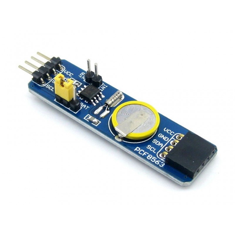
Pcf8563 Rtc Board For Raspberry Pi Real Time Clock Module Blue
Rs. 71.00 Rs. 86.00
- Product Code: SEN-RTC
- Availability: In Stock
- Price in reward points: 1
- For Bulk Order
 9962060070
- The PCF8563 RTC Board provides the real-time clock/calendar function, which can be driven by a battery on board and works independently even when the MCU is turned off.
- The PCF8563 RTC Board features I2C pin-header on one side and I2C connector on the opposite side. Hence, it’s more flexible to connect the board to your development system. The board also supports I2C cascading, allowing the use of multi-module connected to the I2C bus at the same time by connecting the pinheader and connector.
Features:
Model: PCF8563
I2C pin header,
SPECIFICATIONS:
IC ChiP CF8563
Battery 3.3V(button)
| OVERVIEW | |
| Model | PCF8563 |
| Weight | 3 gm. |
| I2C pin header, | |
| 3.3V battery. | |
| Dimensions | 61 x 16 x 11 mm (LxWxH). |
PACKAGE INCLUDES:
1 PCS x Pcf8563 Rtc Module Raspberry Pi
//SOURCE CODE TAKEN FROM BELOW LINK
//http://arduinolearning.com/code/arduino-pcf8563-rtc-example.php
/* Demonstration of Rtc_Pcf8563 Alarms.
*
* The Pcf8563 has an interrupt output, Pin3.
* Pull Pin3 HIGH with a resistor, I used a 10kohm to 5v.
* I used a RBBB with Arduino IDE, the pins are mapped a
* bit differently. Change for your hw.
* SCK - A5, SDA - A4, INT - D3/INT1
*
* After loading and starting the sketch, use the serial monitor
* to see the clock output.
*
* setup: see Pcf8563 data sheet.
* 1x 10Kohm pullup on Pin3 INT
* No pullups on Pin5 or Pin6 (I2C internals used)
* 1x 0.1pf on power
* 1x 32khz chrystal
*
* Joe Robertson, jmr
* orbitalair@bellsouth.net
*/
#include <Wire.h>
#include <Rtc_Pcf8563.h>
/* get a real time clock object */
Rtc_Pcf8563 rtc;
/* a flag for the interrupt */
volatile int alarm_flag=0;
/* the interrupt service routine */
void blink()
{
alarm_flag=1;
}
void setup()
{
pinMode(3, INPUT); // set pin to input
digitalWrite(3, HIGH); // turn on pullup resistors
Serial.begin(9600);
/* setup int on pin 3 of arduino */
attachInterrupt(1, blink, FALLING);
/* clear out all the registers */
rtc.initClock();
/* set a time to start with.
* day, weekday, month, century, year */
rtc.setDate(14, 6, 3, 0, 10);
/* hr, min, sec */
rtc.setTime(1, 15, 40);
/* set an alarm for 20 secs later...
* alarm pin goes low when match occurs
* this triggers the interrupt routine
* min, hr, day, weekday
* 99 = no alarm value to be set
*/
rtc.setAlarm(16, 99, 99, 99);
}
void loop()
{
/* each sec update the display */
Serial.print(rtc.formatTime());
Serial.print(" ");
Serial.print(rtc.formatDate());
Serial.print(" 0x");
Serial.print(rtc.getStatus2(), HEX);
Serial.print("\r\n");
delay(1000);
if (alarm_flag==1){
clr_alarm();
}
}
void clr_alarm()
{
detachInterrupt(1);
Serial.print("blink!\r\n");
rtc.clearAlarm();
delay(1000);
alarm_flag=0;
attachInterrupt(1, blink, FALLING);
}
15 days


