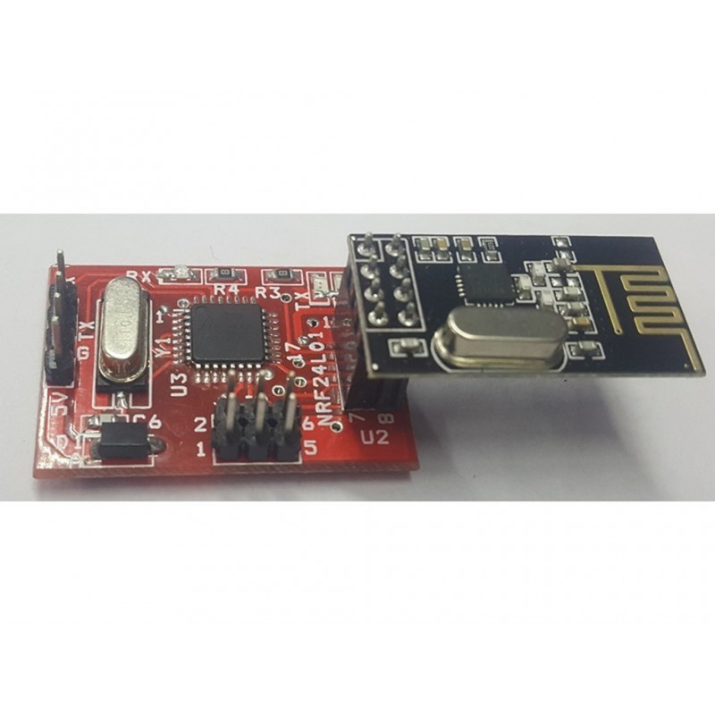
DESCRIPTION:
-The nRF24L01 is a single chip 2.4GHz transceiver with an embedded baseband protocol engine (Enhanced ShockBurst™), designed for ultra low power wireless applications.
-The nRF24L01 is designed for operation in the world wide ISM frequency band at 2.400 - 2.4835GHz.
-An MCU (microcontroller) and very few external passive components are needed to design a radio system with the nRF24L01.
-The nRF24L01 is configured and operated through a Serial Peripheral Interface (SPI).
-The register map contains all configuration registers in the nRF24L01 and is accessible in all operation modes of the chip.
-The embedded baseband protocol engine (Enhanced ShockBurst™) is based on packet communication and supports various modes from manual operation to advanced autonomous protocol operation. Enhanced ShockBurst™ reduces system cost by handling all the high-speed link layer operations.
-The radio front end uses GFSK modulation. It has user configurable parameters like frequency channel, output power and air data rate.
-Internal voltage regulators ensure a high Power Supply Rejection Ratio (PSRR) and a wide power supply range.
NOTE:
The distance covered for data transfer is 100metre.
FEATURES:
-Worldwide 2.4GHz ISM band operation
-Up to 2Mbps on air data rate • Ultra low power operation
-11.3mA TX at 0dBm output power
-12.3mA RX at 2Mbps air data rate
-900nA in power down
-22µA in standby-I
-On chip voltage regulator
-1.9 to 3.6V supply range
-Enhanced ShockBurst™
-Automatic packet handling
-Auto packet transaction handling
-6 data pipe MultiCeiver™
-Air compatible with nRF2401A, 02, E1 and E2
-Low cost BOM
-±60ppm 16MHz crystal
-5V tolerant inputs
-Compact 20-pin 4x4mm QFN package.
CONNECTION STEPS:
-Connect 5v power supply to NRF24L01TTL
-When connect the power supply “LED will blink”
-Connect Tx pin of NRF24L0TTL to microcontroller Rx pin
-Connect Rx pin of NRF24L0TTL to microcontroller Tx pin
-When data passing through Microcontroller then Rx LED of NRF24L01TTL will blink
-Both transmitter and receiver address bit should be in even.
NOTE:
If address bit switches are changed then need to press reset.
APPLICATIONS:
-Wireless PC Peripherals
-Mouse, keyboards and remotes
-3-in-one desktop bundles
-Advanced Media centre remote controls
-VoIP headsets
-Game controllers
-Sports watches and sensors
-RF remote controls for consumer electronics
-Home and commercial automation
-Ultra low power sensor networks
-Active RFID
-Asset tracking systems
The circuit:
* RX is digital pin 10 (connect to TX of other device)
* TX is digital pin 11 (connect to RX of other device)
*/
#include <SoftwareSerial.h>
SoftwareSerial mySerial(10, 11); // RX, TX
void setup() { // Open serial communications and wait for port to open:
Serial.begin(9600);
while (!Serial) {
; // wait for serial port to connect. Needed for native USB port only
}
Serial.println("Goodnight moon!");
// set the data rate for the SoftwareSerial port
mySerial.begin(9600);
mySerial.println("Hello, world?");
}
void loop()
{ // run over and over
if (mySerial.available()) { // if data available in NRF
Serial.write(mySerial.read()); // then transmits to PC
}
if (Serial.available()) { // if data available in PC
mySerial.write(Serial.read()); // then transmits to NRF
}
}
 9962060070
