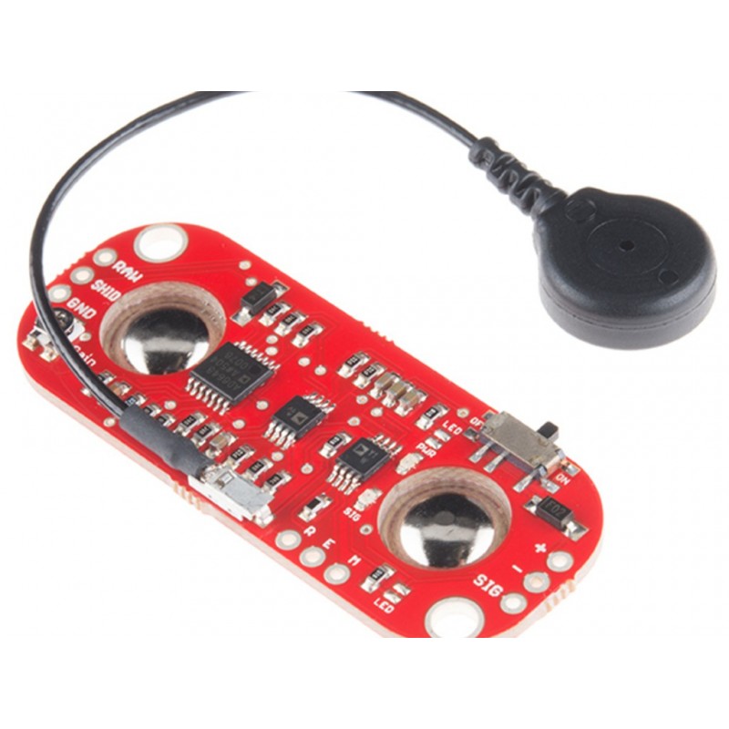
Myoware Muscle Sensor
Rs. 829.00 Rs. 995.00
- Brand: http://www.advancertechnologies.com/p/myoware.html
- Product Code: SEN-BIOMEDICAL
- Availability: 2-3 Days
- Price in reward points: 41
- For Bulk Order
 9962060070
The MyoWare Muscle Sensor is the state-of-the-art revision of the Muscle Sensor of old, now with a new wearable design that allows you to connect biomedical sensor pads without delay to the board itself getting rid of those pesky cables.
This new board also includes a slew of other new functions consisting of, unmarried-deliver voltage of +three.1V to +5V, RAW EMG output, polarity protected strength pins, indicator LEDs, and (subsequently) an On/Off switch.
Additionally, we've got advanced a few shields (Cable, Power, and Proto) which can attach to the Myoware Muscle Sensor to help growth its versatility and functionality!
Measuring muscle interest via detecting its electric ability, known as electromyography (EMG), has traditionally been used for scientific research.
However, with the arrival of ever shrinking yet extra powerful microcontrollers and integrated circuits, EMG circuits and sensors have found their way into all types of control structures.
SPECIFICATIONS:
-Wearable Design
-Single Supply
-+2.9V to +5.7V
-Polarity reversal protection
-Two Output Modes
-EMG Envelope
-Raw EMG
-Expandable via Shields
-LED Indicators
-Specially Designed For Microcontrollers
-Adjustable Gain
OVERVIEW:
-NEW - Wearable Design
-NEW - Single Supply
-+2.9V to +5.7V
-Polarity reversal protection
-NEW - Two Output Modes
-EMG Envelope
-Raw EMG
-NEW - Expandable via Shields
-NEW - LED Indicators
-Specially Designed For Microcontrollers
-Adjustable Gain
PACKAGE INCLUDES:
1 PCS x Myoware Muscle Sensor
http://www.advancertechnologies.com/p/myoware.html
//*SOURCE CODE TAKEN FROM BELOW LINK
//https://www.arduino.cc/en/Tutorial/BuiltInExamples/ReadAnalogVoltage/
ReadAnalogVoltage
Reads an analog input on pin 0, converts it to voltage, and prints the result to the Serial Monitor.
Graphical representation is available using Serial Plotter (Tools > Serial Plotter menu).
Attach the center pin of a potentiometer to pin A0, and the outside pins to +5V and ground.
This example code is in the public domain.
http://www.arduino.cc/en/Tutorial/ReadAnalogVoltage
*/
// the setup routine runs once when you press reset:
void setup() {
// initialize serial communication at 9600 bits per second:
Serial.begin(9600);
}
// the loop routine runs over and over again forever:
void loop() {
// read the input on analog pin 0:
int sensorValue = analogRead(A0);
// Convert the analog reading (which goes from 0 - 1023) to a voltage (0 - 5V):
float voltage = sensorValue * (5.0 / 1023.0);
// print out the value you read:
Serial.println(voltage);
}
15 days


