Arduino Esplora Game Based Board With Integrated Joystick And Keys
Rs. 1,357.00 Rs. 1,561.00
- Brand: https://store.arduino.cc/usa/arduino-esplora
- Product Code: ARDUINO
- Availability: In Stock
- Price in reward points: 11
- For Bulk Order
 9962060070
DESCRIPTION:
-The ESPLORA Joystick Photosensitive Sensor Board is a microcontroller board compatible with Arduino & derived from the Arduino Leonardo.
-The ESPLORA Joystick Photosensitive Sensor Board differs from all preceding Arduino boards in that it provides a number of built-in; ready-to-use set of onboard sensors for interaction.
-It’s designed for people who want to get up and running with Arduino without having to learn about the electronics first.
-For a step-by-step introduction to the Esplora; check out the Getting Started with Esplora guide.
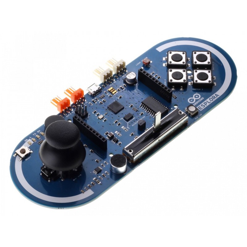
-The ESPLORA Joystick Photosensitive Sensor Board has onboard sound and light outputs, and several input sensors; including a joystick, a slider, a temperature sensor, an accelerometer, a microphone, and a light sensor.
-It also has the potential to expand its capabilities with two Tinker-kit input and output connectors, and a socket for a color TFT LCD screen.
-Like the Leonardo board, the ESPLORA Joystick Photosensitive Sensor Board uses an Atmega32U4 AVR microcontroller with 16 MHz crystal oscillator.
-And a micro USB connection capable of acting as a USB client device like a mouse or a keyboard.
-In the upper left corner of the board, there is a reset push button, that you can use to restart the board.
-There are four status LEDs
-ON [green] indicates whether the board is receiving power supply.
-L [yellow] connect directly to the micro-controller, accessible through pin 13.
-RX and TX [yellow] indicates the data being transmit or receive over the USB communication.
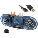
-The board contains everything need to support the microcontroller; simply connect it to a computer with a USB cable to get started.
-The Esplora has built-in USB communication; it can appear to a connected computer as a mouse or keyboard, in addition to a virtual (CDC) serial / COM port.
-This has other implications for the behavior of the board; these are detailed on the getting started page.
-You can find all the information you need to configure your board, use the Arduino Software (IDE); and start to tinker with coding and electronics.
Input and Output
-The design of the ESPLORA Joystick Photosensitive Sensor Board recalls traditional gamepad design with an analog joystick on the left and four push buttons on the right.
-The ESPLORA Joystick Photosensitive Sensor Board has the following onboard inputs and outputs :
-Analog joystick with central push-button two axes (X and Y) and a center pushbutton.
-4 push-buttons laid out in a diamond pattern.
-Linear potentiometer slider near the bottom of the board.
-Microphone for getting the loudness (amplitude) of the surrounding environment.
-Light sensor for getting the brightness.
-Temperature sensor reads the ambient temperature.
-Three-axis accelerometer measures the board’s relation to gravity on three axes (X, Y, and Z).
-The buzzer can produce square-waves.
-RGB led bright LED with Red Green and Blue elements for color mixing.
-2 TinkerKit Inputs to connect the TinkerKit sensor modules with the 3-pin connectors.
-2 TinkerKit Outputs to connect the TinkerKit actuator modules with the 3-pin connectors.
-TFT display connector for an optional color LCD screen; SD card, or other devices that use the SPI protocol.
-In order to utilize the total number of available sensors, the board uses an analog multiplexer. This means a single analog input of the microcontroller is shared among all the input channels (except the 3-axis accelerometer).
-Four additional microcontroller pins choose which channel to read.
Communication:
-The Leonardo the ESPLORA Joystick Photosensitive Sensor Board has a number of facilities for communicating with a computer; another Arduino, or other micro-controllers.
-The ATmega32U4 provides serial (CDC) communication over USB and appears as a virtual com port software on the computer. The chip also acts as a full speed USB 2.0 device, using standard USB COM drivers.
-On Windows, a .inf file requires.
-The Arduino software includes a serial monitor which allows simple textual data to be sent to and from the Arduino board. --The RX and TX LEDs on the board will flash when data is transmitting via the USB connection to the computer.
-The ATmega32U4 also supports SPI communication, that access through the SPI library.
-The Esplora can appear as a generic keyboard and mouse and can be a program to control these input devices using the Keyboard and Mouse libraries.
Programming:
-The Esplora can be the program with the Arduino software (download).
-Select “Esplora” from the Tools > Board menu. For details, see the getting started page.
-The ATmega32U4 on the Esplora comes pre-burn with a boot-loader that allows you to upload new code to it without the use of an external hardware programmer.
-It communicates using the AVR109 protocol.
-You can also bypass the bootloader and program the microcontroller through the ICSP (In-Circuit Serial Programming) header; see these instructions for details.
-To facilitate writing sketches for the Esplora; there is a dedicated library that contains methods for reading the sensors and writing to the outputs onboard.
-The library offers high-level methods which provide pre-process data, like degrees Fahrenheit or Celsius from the temperature sensor.
-It also enables easy access to the outputs, like writing values to the RGB LED.
-Visit the Esplora library reference page to see the complete documentation of the library and examples.
Automatic (Software) Reset and Bootloader initiation :
-Rather than requiring a physical press of the reset button before an upload; the Esplora is designing in a way that allows it to be reset by software running on a connected computer.
-The reset is trigger when the Esplora’s virtual (CDC) serial / COM port is open at 1200 baud and then close.
-When this happens, the processor will reset, breaking the USB connection to the computer (meaning that the virtual serial / COM port will disappear).
-After the processor resets, the boot-loader starts, remaining active for about 8 seconds.
-The boot-loader can also be initiate by pressing the reset button on the Esplora.
-Note that when the board first powers up, it will jump straight to the user sketch; if present, rather than initiating the boot-loader.
-Because of the way the Esplora handles reset it’s best to let the Arduino software try to initiate the reset before uploading; especially if you are in the habit of pressing the reset button before uploading on other boards.
-If the software can’t reset the board you can always start the boot-loader by pressing the reset button on the board.
USB Overcurrent Protection :
-The Esplora has a re-settable poly-fuse that protects your computer’s USB ports from shorts and over-current. Although most computers provide their own internal protection, the fuse provides an extra layer of protection.
-If more than 500 mA is applied to the USB port, the fuse will automatically break the connection until the short or overload is removed.
Physical Characteristics :
-The maximum length and width of the Esplora PCB are 6.5 and 2.4 inches respectively, with the USB and TinkerKit connectors extending beyond the latter dimension.
-Four screw holes allow the board to be attached to a surface or case.
| SPECIFICATIONS: | |
| Microcontroller | ATmega32U4 |
| Operating Voltage(VDC) | 5 |
| Flash Memory | 32KB |
| SRAM | 2.5KB |
| EEPROM | 1KB |
| Clock Speed | 16 MHz |
| OVERVIEW: | |
| Microcontroller | ATmega32u4 |
| Operating Voltage | 5V |
| Flash Memory | 32 KB of which 4 KB used by bootloader |
| SRAM | 2.5 KB |
| EEPROM | 1 KB |
| Clock Speed | 16 MHz |
PACKAGE INCLUDES:
1 PCS x Arduino Esplora Game Based Board With Integrated Joystick And Keys
https://store.arduino.cc/usa/arduino-esplora
https://youtu.be/kHBIoHwN3e8
15 days

