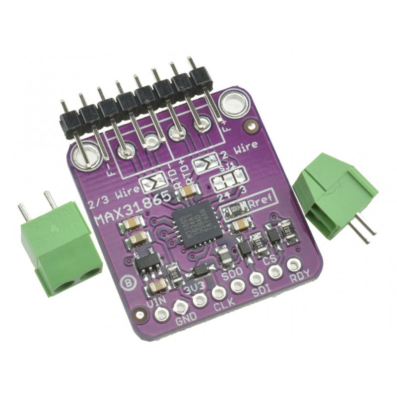
Cjmcu 31865 Max31865 Rtd Platinum Pt100 To Pt1000 Temperature To Digital Voltage Converter
Rs. 789.00 Rs. 908.00
- Brand: https://www.maximintegrated.com/en/products/interface/sensor-int
- Product Code: SEN-TEMP
- Availability: In Stock
- Price in reward points: 3
- For Bulk Order
 9962060070
| SPECIFICATIONS | |
| Supply Voltage | 3- 5V |
| Supply Current | 10mA. |
| Voltage | Regulator type |
| Model No | MAX31865 |
OVERVIEW:
-Supply Voltage: 3 - 5V
-Supply Current: 10mA.
-Voltage Regulator type
-Model No. MAX31865
PACKAGE INCLUDES:
1 PCS x Cjmcu 31865 Max31865 Rtd Platinum Pt100 To Pt1000 Temperature To Digital Voltage Converter
https://www.maximintegrated.com/en/products/interface/sensor-interface/MAX31865.html
//SOURCE CODE TAKEN FROM BELOW LINK
//https://github.com/hallard/arduino-max31865/blob/master/Examples/Full_Test_Serial/Full_Test_Serial.ino
/ ****************************************************************************
// MAX31865 Break-out board Full test Example on Serial
// *****************************************************************************
//
// For any explanation on this breakout board
// look at my blog post here http://hallard.me/max31865
//
// Written by Charles-Henri Hallard (http://hallard.me)
//
// History : V1.00 2015-07-14 - First release
//
// This sketch as been tested on early ULPNode prototype called ArduiNode
// see https://github.com/hallard/ULPNode/tree/master/hardware/ArduiNode
// where MAX31865 breakout board was plugged in
//
// It should work on any 3.3V (if 5V you need to add level converters) boards
// such as Arduino/Clone as soon as connections are as follow
//
// Arduino Uno --> MAX31865 break out board
// -------------------------------------------
// 3V3 (!not 5V) --> NRF Connector pin 8 (VCC)
// GND --> NRF Connector pin 1 (GND)
// CS: pin D10 --> NRF Connector pin 7 (CSN)
// MOSI: pin D11 --> NRF Connector pin 6 (MOSI)
// MISO: pin D12 --> NRF Connector pin 4 (MISO)
// SCK: pin D13 --> NRF Connector pin 3 (SCK)
//
// Optional IRQ and LED (set #define below)
// -------------------------------------------
// IO pin D8 --> NRF Connector pin 2 (LED)
// IRQ: pin D2 --> NRF Connector pin 5 (IRQ)
//
// Optional OLED I2C Display
// (4K7 Pullup on SDA/SCL recommended)
// Arduino Uno --> 128x*64 OLED Display
// -------------------------------------------
// 3V3 --> OLED 3V3
// GND --> OLED GND
// SDA pin A4 --> OLED I2C SDA
// SCL pin A5 --> OLED I2C SCL
//
// Dependencies
// ============
// u8glib library see https://github.com/olikraus/U8glib_Arduino
//
// *****************************************************************************
// This program is free software: you can redistribute it and/or modify
// it under the terms of the GNU General Public License as published by
// the Free Software Foundation, either version 3 of the License, or
// (at your option) any later version.
//
// This program is distributed in the hope that it will be useful,
// but WITHOUT ANY WARRANTY; without even the implied warranty of
// MERCHANTABILITY or FITNESS FOR A PARTICULAR PURPOSE. See the
// GNU General Public License for more details.
//
// You should have received a copy of the GNU General Public License
// along with this program. If not, see <http://www.gnu.org/licenses/>.
//
// All text above must be included in any redistribution.
//
// *****************************************************************************
#include <avr/power.h>
#include <SPI.h>
#include <MAX31865.h>
#include <Wire.h>
// define here PT1000 or PT100
// ===========================
#define PT1000
//#define PT100
// define here false for 2 wires
// true for 3/4 wires
// ==============================
#define USE_3WIRES false
//#define USE_3WIRES true
// Led on MAX31865 Break-out Board
#define LED_MAX31865 8
// Data Ready Signal on MAX31865 Break-out Board
// Comment if you did not connected te IRQ signal of
// breakout board to a IO, else set IO here
#define DRDY_MAX31865 2
// Chip Select Pin
#define RTD_CS_PIN 10
// MAX31865 device status seen on SPI bus or not
// This is before device internal status register
#define MAX31865_STATE_NOT_FOUND 0
#define MAX31865_STATE_TRANSMIT_ERROR 1
#define MAX31865_STATE_OK 2
#define MAX31865_RTD_CONFIG_FAULT 3
// Do measure every 2 seconds
#define MEASURE_INTERVAL 2000L
// mask to know where to print data
#define PRINT_MODE_SERIAL 0x01
#define PRINT_MODE_OLED 0x02
#define PRINT_MODE_BOTH (PRINT_MODE_SERIAL | PRINT_MODE_OLED)
// Got some of old Arduinode revisions and prototype boards
// so I need specifc setup to define board type to adjust the pin
// mapping depending on the board used during my tests
// Early ULPNode board (I use on this one but it's not mandatory)
// See https://github.com/hallard/ULPNode/tree/master/hardware/ArduiNode
// for schematics of this little test board
// Don't worry, it works on any board, it's just my specific settings
#ifdef ARDUINO_ARDUINODE_V13
#define RF_IRQ 2
#define SW_IRQ 3
#define LED_BLU 4
#define LED_GRN 5
#define LED_RED 6
#define OLED_POWER_PIN 7
#define RF_CE 8
#define RF_POWER_PIN 9
#define RF_SS 10
#define VBATT A1
#define SENSOR_POWER_PIN A2
#define SENSOR_DHT_DQ A3
#define SENSOR_NTC A6
#define SENSOR_LIGHT A7
#define rfPWR_ON() digitalWrite(RF_POWER_PIN, LOW)
#define rfPWR_OFF() digitalWrite(RF_POWER_PIN, HIGH)
#define sensorPWR_ON() digitalWrite(SENSOR_POWER_PIN, HIGH)
#define sensorPWR_OFF() digitalWrite(SENSOR_POWER_PIN, LOW)
#define oledPWR_ON() digitalWrite(OLED_POWER_PIN, LOW)
#define oledPWR_OFF() digitalWrite(OLED_POWER_PIN, HIGH)
// turn the LED on (Arduino pin = 1 = Led ON because of hardware, change if needed)
//
// R LED
// GND +----===----|<|----- Aruino Pin
//
#define ledON(x) digitalWrite(x, HIGH)
#define ledOFF(x) digitalWrite(x, LOW)
#endif
// see MAX31865 datasheet page 20/21
// Table 9. Temperature Example for PT100 with 400Ω RREF
// to set Min Max temps (value)
#define FAULT_HIGH_THRESHOLD 0x9304 /* +350C */
#define FAULT_LOW_THRESHOLD 0x2690 /* -100C */
//#define FAULT_HIGH_THRESHOLD 0xBE64 /* +550C */
//#define FAULT_LOW_THRESHOLD 0x0BDA /* -200C */
#ifdef PT1000
// For PT 1000 (Ref on breakout board = 3900 Ohms 0.1%)
MAX31865_RTD rtd( MAX31865_RTD::RTD_PT1000, RTD_CS_PIN, 3900 );
#endif
#ifdef PT100
// For PT 100 (Ref Ref on breakout board = 390 Ohms 0.1%)
MAX31865_RTD rtd( MAX31865_RTD::RTD_PT100, RTD_CS_PIN, 390 );
#endif
// Error message associated to status
uint8_t status;
String status_text;
char buffer[32]; // Temp buffer for formating string/display text
// MAX31865 device status seen on SPI bus or not
uint8_t max31865_state = MAX31865_STATE_NOT_FOUND;
/* ======================================================================
Function: status2text
Purpose : convert status to human readable text
Input : status register of MAX31865
Output : pointer to error string
Comments: -
====================================================================== */
String status2text(uint8_t status)
{
// Default
status_text = "";
if( status == 0 )
status_text += F("OK!");
else {
if( status & MAX31865_FAULT_HIGH_THRESHOLD )
status_text += F("RTD high thre. exceeded ");
if( status & MAX31865_FAULT_LOW_THRESHOLD )
status_text += F("RTD low thres. exceeded ");
if( status & MAX31865_FAULT_REFIN )
status_text += F("REFIN- > 0.85x V_BIAS ");
if( status & MAX31865_FAULT_REFIN_FORCE )
status_text += F("REFIN- < 0.85x V_BIAS F- Open ");
if( status & MAX31865_FAULT_RTDIN_FORCE )
status_text += F("RTDIN- < 0.85x V_BIAS F- Open ");
if( status & MAX31865_FAULT_VOLTAGE )
status_text += F("Overvoltage / undervoltage ");
}
return (status_text);
}
/* ======================================================================
Function: setup
Purpose : init arduino stuff
Input : -
Output : -
Comments: -
====================================================================== */
void setup()
{
#ifdef ARDUINO_ARDUINODE_V13
// Set clock to 16MHZ
clock_prescale_set(clock_div_1);
#endif
// Init Serial Port
Serial.begin( 115200 );
Serial.println(F("===================="));
Serial.println(F(__FILE__));
Serial.println(F(__DATE__ " " __TIME__ "\r\n"));
/* Initialize SPI communication. */
// device can go up to 5MHz, set it to 4MHz
SPI.begin();
SPI.setClockDivider( SPI_CLOCK_DIV4 );
SPI.setDataMode( SPI_MODE1 );
// Ports Initialization
// ====================
// Led as output
#ifdef ARDUINO_ARDUINODE_V13
pinMode(LED_GRN, OUTPUT);
pinMode(LED_BLU, OUTPUT);
ledOFF(LED_GRN);
ledOFF(LED_BLU);
ledOFF(LED_RED);
// Power pin that control module (On/Off)
pinMode(RF_POWER_PIN, OUTPUT);
pinMode(SENSOR_POWER_PIN, OUTPUT);
pinMode(OLED_POWER_PIN, OUTPUT);
// Power them all
rfPWR_ON();
sensorPWR_ON();
oledPWR_ON();
#endif
pinMode(10, OUTPUT); // SPI SS (avoid becoming SPI Slave)
#ifdef LED_MAX31865
pinMode(LED_MAX31865, OUTPUT); // RFM breakout board LED
// small blink
digitalWrite(LED_MAX31865, 0);
delay(50);
digitalWrite(LED_MAX31865, 1);
#endif
#ifdef DRDY_MAX31865
pinMode(DRDY_MAX31865, INPUT_PULLUP); // RFM breakout board DRDY
#endif
#ifdef ARDUINO_ARDUINODE_V13
// Small light to indicate we're all fine
ledON(LED_GRN);
delay(25);
ledOFF(LED_GRN);
ledON(LED_RED);
delay(25);
ledOFF(LED_RED);
ledON(LED_BLU);
delay(25);
ledOFF(LED_BLU);
#endif
// Allow display reading and MAX31865 to warm up
delay( 1000 );
}
/* ======================================================================
Function: loop
Purpose : main Arduino loop
Input : -
Output : -
Comments: read temperature and display on serial and OLED
====================================================================== */
void loop()
{
static unsigned long lastRefreshed = 0;
uint8_t status;
// Do measure every MEASURE_INTERVAL (in ms) ?
if( millis()-lastRefreshed >= MEASURE_INTERVAL)
{
// reset our last measure
lastRefreshed += MEASURE_INTERVAL;
// default not found
max31865_state = MAX31865_STATE_NOT_FOUND;
Serial.print( millis()/1000);
Serial.print(F("\tChecking MAX31865 SPI chip..."));
// Indicate onboard MAX31865 we do a measure
#ifdef LED_MAX31865
digitalWrite(LED_MAX31865, 0);
#endif
/* Reconfigure this allow us to plug/unplug the module and check PT100/PT1000
V_BIAS enabled
No Auto-conversion
1-shot disabled
3-wire
Fault detection: we need to manual mode, set manual 1 => First stage
because on MAX31865 beakout board, RC constant is > 100us
see MAX31865 datasheet page 14 / Section Fault Detection Cycle (D3:D2)
Fault status: auto-clear
50 Hz filter
Low threshold: FAULT_LOW_THRESHOLD
High threshold: FAULT_HIGH_THRESHOLD
*/
// 1st do full configuration, enable vbias and wait 5*RC constant
// see MAX31865 datasheet page 14 / Section Fault Detection Cycle (D3:D2)
rtd.configure( true, false, false, USE_3WIRES, MAX31865_FAULT_DETECTION_NONE,
true, true, FAULT_LOW_THRESHOLD, FAULT_HIGH_THRESHOLD );
//delay(60);
// We will read back thresold, to check it's same we wrote
rtd.read_all( );
// Spi read 0xffff or 0x0000, mainly no com with device
if ( ( rtd.low_threshold()== 0x0 || rtd.low_threshold() == 0xffff ) &&
( rtd.high_threshold()== 0x0 || rtd.high_threshold()== 0xffff ) )
{
#ifdef ARDUINO_ARDUINODE_V13
ledOFF(LED_BLU);
#endif
max31865_state = MAX31865_STATE_NOT_FOUND;
Serial.println(F("No communication, is breakout board plugged ?"));
// Blue LED off (on = indicate MAX31865 seen and talk)
}
// we found something, but not what we wrote on threshold registers, bad com!!!
else if ( (rtd.low_threshold()!= FAULT_LOW_THRESHOLD) || (rtd.high_threshold()!=FAULT_HIGH_THRESHOLD))
{
// Blue LED off (on = indicate MAX31865 seen and talk)
#ifdef ARDUINO_ARDUINODE_V13
ledOFF(LED_BLU);
#endif
max31865_state = MAX31865_STATE_TRANSMIT_ERROR;
Serial.println(F("SPI transmission error, verify wiring!"));
Serial.print(F("\t Set low threshold to 0x"));
Serial.print( FAULT_LOW_THRESHOLD,HEX);
Serial.print(F( " just read 0x"));
Serial.println( rtd.low_threshold(),HEX);
Serial.print(F( "\t Set high threshold to 0x"));
Serial.print( FAULT_HIGH_THRESHOLD,HEX);
Serial.print(F( " just read 0x"));
Serial.println( rtd.high_threshold(),HEX);
}
// ok all seems fine untils there we can talk to device to do action
else
{
// Blue LED indicate MAX31865 seen and talk
#ifdef ARDUINO_ARDUINODE_V13
ledON(LED_BLU);
#endif
max31865_state = MAX31865_STATE_OK;
Serial.println(F("Found OK!"));
Serial.print(F("\t Checking manual fault detection Stage 1 "));
// Stage 1
// Now we're ready to start fault detection (RTD connection)
// V_BIAS enabled , No Auto-conversion, 1-shot disabled, Fault detection Stage 1
rtd.configure( true, false, false, MAX31865_FAULT_DETECTION_MANUAL_1 );
// wait some time MAX31865 has finished the test
// no indication in datasheet on how much time it take
// but without this delay value returned is not 0x20 but 0x00
delay(2);
// After stage 1, fault status should return 0x20
// MAX31865 datasheet page 14 / Section Fault Detection Cycle (D3:D2)
sprintf_P(buffer, PSTR("status=%02X => OK!"), rtd.fault_status() );
Serial.println(buffer);
Serial.print(F("\t Checking manual fault detection Stage 2 "));
// Wait 5 * RC constant before stage 2
// see MAX31865 datasheet page 14 / Section Fault Detection Cycle (D3:D2)
delay(60);
// Stage 2
// V_BIAS enabled , No Auto-conversion, 1-shot disabled,
rtd.configure( true, false, false, MAX31865_FAULT_DETECTION_MANUAL_2 );
// wait some time MAX31865 has finished the test
// no indication in datasheet on how much time it take
// but without this delay value returned may be inconsistent
delay(2);
// ok what device is saying about Fault Detection ?
status = rtd.fault_status();
sprintf_P(buffer, PSTR("status=%02X => "), status );
Serial.print(buffer);
status2text(status);
Serial.println(status_text);
// Ok all wnet fine ? we'll do a measure
if (status==0 )
{
max31865_state = MAX31865_STATE_OK;
Serial.print(F("\t Starting conversion..."));
// Start 1 shot measure
// V_BIAS enabled , No Auto-conversion, 1-shot enabled, No Fault detection
rtd.configure( true, false, true, MAX31865_FAULT_DETECTION_NONE );
// onboard MAX31865 will push DRDY line low when measure's done
#ifdef DRDY_MAX31865
// Time out start
unsigned long timeout = millis();
// wait chip says finished or timeout (datasheet says max 66ms)
while ( digitalRead(DRDY_MAX31865)==1 && millis()-timeout < 70);
if ( millis()-timeout>=70)
// Display conversion time
Serial.print(F("(timed-out "));
else
// Display conversion time
Serial.print(F("(in "));
Serial.print(millis()-timeout,DEC);
Serial.print(F("ms) "));
#else
// 50 Hz max conversion time in one shot
delay(70);
#endif
// Read MAX31865 all registers values
status = rtd.read_all();
sprintf_P(buffer, PSTR("Status:%02X "), status );
Serial.println(buffer);
Serial.print(F( "\t RTD:"));
Serial.print( rtd.raw_resistance());
// display temperature reading on serial
double temperature = rtd.temperature();
Serial.print(F( " Ohms => Temp:"));
Serial.print( temperature,1);
Serial.println(F(" C" ));
}
// disable V_BIAS and one shot to reduce power
rtd.configure( false, false, false, MAX31865_FAULT_DETECTION_NONE);
} // device seen
// All is good ?
if( max31865_state==MAX31865_STATE_OK && status==0 && rtd.raw_resistance()!=0 )
{
// We displayed all, add what you want there
}
#ifdef LED_MAX31865
// measure done
digitalWrite(LED_MAX31865, 1);
#endif
Serial.println(F("\tDone!\r\n"));
}
// Manage blink led (Red error, Green OK)
#ifdef ARDUINO_ARDUINODE_V13
uint8_t led ;
led = status==0?LED_GRN:LED_RED;
if (millis() % 200 < 50 )
ledON(led);
else
ledOFF(led);
#endif
}
15 days


