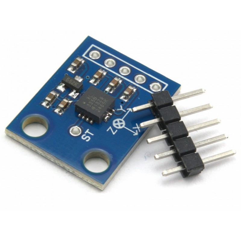
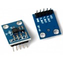
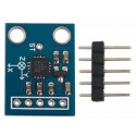
Adxl335 Module 3 Axis Analog Output Accelerometer
Rs. 350.00 Rs. 392.00
- Brand: https://www.analog.com/en/products/adxl335.html
- Product Code: SEN-ACCELEROMETER
- Availability: In Stock
- Price in reward points: 3
- For Bulk Order
 9962060070
| SPECIFICATIONS: | |
| Supply Voltage (V) | 3 to 6 |
| Each Axis Bandwidth | 50Hz |
| Operating Temperature (°C) | -40 to +90 |
| Length (mm) | 21 |
| Width (mm) | 16 |
| Height (mm) | 2.5 |
| Weight (gm) | 0.6 |
| Shipment Weight | 0.085 kg |
| Shipment Dimensions | 4 × 3 × 1 cm |
OVERVIEW:
-Onboard LDO Voltage regulator
-Can be interfaced with 3V3 or 5V Microcontroller.
-Tap/Double Tap Detection
-Free-Fall Detection
-Analog output
-Build in ultra low noise linear LDO voltage regulator
-Built-in onboard filters, which reduce noise from the motor and other high current electronics
-You can easily select two I2C address for MPU6050 by soldered jumper
-Power LED
-Build in Logic level converter for I2C
PACKAGE INCLUDES:
1 PCS x Adxl335 Module 3 Axis Accelerometer Analog Output
https://www.analog.com/en/products/adxl335.html
//SOURCE CODE TAKEN FROM BELOW LINK
//https://content.instructables.com/pdfs/EAN/KB3E/HNRL5MCQ/Interfacing-ADXL335-with-ARDUINO.pdf
//connection
//The accelerometer module has 5 pins, namely
//GND-To be connected to Arduino's GND
//VCC-To be connected to Arduino's 5V
//X-To be connected to Analog Pin A5
//Y-To be connected to Analog Pin A4
//Z-To be connected to Analog Pin A3
//output
//We will be displaying two different values for one analog value read. The first value is the ADC //converted value in 10-bit resolution(0 to 1023) while the second one is mapped for PWM and it is in 8bit //resolution(0 to 255).
//Three values for X, Y & Z axes are displayed together are repeated after an interval of 3 seconds.
const int ap1 = A5;
const int ap2 = A4;
const int ap3 = A3;
int sv1 = 0;
int ov1 = 0;
int sv2 = 0;
int ov2= 0;
int sv3 = 0;
int ov3= 0;
void setup() {
// initialize serial communications at 9600 bps:
Serial.begin(9600);
}
void loop() {
analogReference(EXTERNAL); //connect 3.3v to AREF
// read the analog in value:
sv1 = analogRead(ap1);
// map it to the range of the analog out:
ov1 = map(sv1, 0, 1023, 0, 255);
// change the analog out value:
delay(2);
//
sv2 = analogRead(ap2);
ov2 = map(sv2, 0, 1023, 0, 255);
//
delay(2);
//
sv3 = analogRead(ap3);
ov3 = map(sv3, 0, 1023, 0, 255);
// print the results to the serial monitor:
Serial.print("Xsensor1 = " );
Serial.print(sv1);
Serial.print("\t output1 = ");
Serial.println(ov1);
Serial.print("Ysensor2 = " );
Serial.print(sv2);
Serial.print("\t output2 = ");
Serial.println(ov2);
Serial.print("Zsensor3 = " );
Serial.print(sv3);
Serial.print("\t output3 = ");
Serial.println(ov3);
delay(3000);
}
15 days

