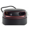
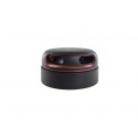
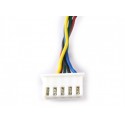
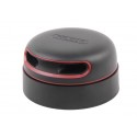
Rp Lidar A2M6 360 Degrees Laser Range Finder 18 Meter Range
Rs. 19,404.00 Rs. 22,121.00
- Brand: https://www.slamtec.com/en/Support#rplidar-a-series
- Product Code: SEN-LIDAR
- Availability: 2-3 Days
- Price in reward points: 354
- For Bulk Order
 9962060070
SPECIFICATIONS:
Model :RP LIDAR A2M6
Distance Range :0.15 – 18m, Based on white objects with 70% reflectivity
Angular Range :0-360 Degree
Distance Resolution :<0.5mm
Angular Resolution :0.45~1.35 degree,Typical 0.9 degree
Sample Duration :0.25ms
Scan Rate :5~15Hz,Typical 10Hz,
Sample Frequency :2000~8000Hz,Typical 4000Hz,
Battery :Excluded
OVERVIEW:
-4cm Ultra-thin
-Ideal for all kinds of service robot.
-8000 times sample rate, the highest in the current economical LIDAR industry
-360-degree laser range scanning
-Low Noise, Brushless Motor New Non-contact Drive
-18m Range Radius
-OPTMAG Original Design, prolong the life-span
-Class 1 Laser Safety Standard
-High-speed RPVision Range Engine: RPVision 2.0
-Five years ultra-long life.
PACKAGE INCLUDES:
1 PCS x Rp Lidar A2M6 360 Degrees Laser Range Finder 18 Meter Range
1 PCS x USB Cable
1 PCS x DC Cable
1 PCS x Adapter Driver Board
https://www.slamtec.com/en/Support#rplidar-a-series
//SOURCE CODE TAKEN FROM BELOW LINK
//https://www.instructables.com/How-to-Use-the-RPLIDAR-360-Laser-Scanner-With-Ardu/
/*
RoboPeak RPLIDAR Arduino Example
This example shows how to control an RGB led based on the scan data of the RPLIDAR
The RGB led will change its hue based on the direction of the closet object RPLIDAR has been detected.
Also, the light intensity changes according to the object distance.
USAGE:
---------------------------------
1. Download this sketch code to your Arduino board
2. Connect the RPLIDAR's serial port (RX/TX/GND) to your Arduino board (Pin 0 and Pin1)
3. Connect the RPLIDAR's motor ctrl pin to the Arduino board pin 3
4. Connect an RGB LED to your Arduino board, with the Red led to pin 9, Blue led to pin 10, Green led to pin 11
5. Connect the required power supplies.
6. RPLIDAR will start rotating when the skecth code has successfully detected it.
7. Remove objects within the 0.5 meters' radius circule range of the RPLIDAR
8. Place some object inside the 0.5 meters' range, check what will happen to the RGB led :)
*/
/*
Copyright (c) 2014, RoboPeak
All rights reserved.
RoboPeak.com
Redistribution and use in source and binary forms, with or without modification,
are permitted provided that the following conditions are met:
1. Redistributions of source code must retain the above copyright notice,
this list of conditions and the following disclaimer.
2. Redistributions in binary form must reproduce the above copyright notice,
this list of conditions and the following disclaimer in the documentation
and/or other materials provided with the distribution.
THIS SOFTWARE IS PROVIDED BY THE COPYRIGHT HOLDERS AND CONTRIBUTORS "AS IS" AND ANY
EXPRESS OR IMPLIED WARRANTIES, INCLUDING, BUT NOT LIMITED TO, THE IMPLIED WARRANTIES
OF MERCHANTABILITY AND FITNESS FOR A PARTICULAR PURPOSE ARE DISCLAIMED. IN NO EVENT
SHALL THE COPYRIGHT HOLDER OR CONTRIBUTORS BE LIABLE FOR ANY DIRECT, INDIRECT, INCIDENTAL,
SPECIAL, EXEMPLARY, OR CONSEQUENTIAL DAMAGES (INCLUDING, BUT NOT LIMITED TO, PROCUREMENT
OF SUBSTITUTE GOODS OR SERVICES; LOSS OF USE, DATA, OR PROFITS; OR BUSINESS INTERRUPTION)
HOWEVER CAUSED AND ON ANY THEORY OF LIABILITY, WHETHER IN CONTRACT, STRICT LIABILITY, OR
TORT (INCLUDING NEGLIGENCE OR OTHERWISE) ARISING IN ANY WAY OUT OF THE USE OF THIS SOFTWARE,
EVEN IF ADVISED OF THE POSSIBILITY OF SUCH DAMAGE.
*/
// This sketch code is based on the RPLIDAR driver library provided by RoboPeak
#include <RPLidar.h>
// You need to create an driver instance
RPLidar lidar;
// Change the pin mapping based on your needs.
/////////////////////////////////////////////////////////////////////////////
#define LED_ENABLE 12 // The GPIO pin for the RGB led's common lead.
// assumes a common positive type LED is used
#define LED_R 9 // The PWM pin for drive the Red LED
#define LED_G 11 // The PWM pin for drive the Green LED
#define LED_B 10 // The PWM pin for drive the Blue LED
#define RPLIDAR_MOTOR 3 // The PWM pin for control the speed of RPLIDAR's motor.
// This pin should connected with the RPLIDAR's MOTOCTRL signal
//////////////////////////////////////////////////////////////////////////////
#include <NeoPixelBus.h>
const uint16_t PixelCount = 24; // this example assumes 4 pixels, making it smaller will cause a failure
const uint8_t PixelPin = 5; // make sure to set this to the correct pin, ignored for Esp8266
#define colorSaturation 64
NeoPixelBus<NeoRgbFeature, Neo800KbpsMethod> strip(PixelCount, PixelPin);
RgbColor red(colorSaturation, 0, 0);
RgbColor green(0, colorSaturation, 0);
RgbColor blue(0, 0, colorSaturation);
RgbColor white(colorSaturation);
RgbColor black(0);
void blackStrip() {
for (int i = 0; i < PixelCount; i++) {
// strip.SetPixelColor(i, leds[i]);
strip.SetPixelColor(i, black);
// leds[i] = black(0);
}
}
void pointangle(int angle) {
// blackStrip();
strip.SetPixelColor(map(angle, 0, 360, 0, 23), green);
strip.Show();
}
void setup() {
// bind the RPLIDAR driver to the arduino hardware serial
strip.Begin();
blackStrip();
strip.Show();
lidar.begin(Serial1);
// set pin modes
pinMode(RPLIDAR_MOTOR, OUTPUT);
}
float minDistance = 100000;
float angleAtMinDist = 0;
int nsbit = 0;
void loop() {
analogWrite(RPLIDAR_MOTOR, analogRead(A0));
if (IS_OK(lidar.waitPoint())) {
//perform data processing here...
float distance = lidar.getCurrentPoint().distance;
float angle = lidar.getCurrentPoint().angle;
if (lidar.getCurrentPoint().startBit) {
nsbit++;
}
if (nsbit > 2) {
// a new scan, display the previous data...
// displayColor(angleAtMinDist, minDistance);
blackStrip();
pointangle(angleAtMinDist);
minDistance = 100000;
angleAtMinDist = 0;
nsbit = 0;
} else {
if ( distance > 0 && distance < minDistance) {
minDistance = distance;
angleAtMinDist = angle;
}
}
} else {
analogWrite(RPLIDAR_MOTOR, 0); //stop the rplidar motor
// try to detect RPLIDAR...
rplidar_response_device_info_t info;
if (IS_OK(lidar.getDeviceInfo(info, 100))) {
//detected...
lidar.startScan();
// analogWrite(RPLIDAR_MOTOR, 255);
analogWrite(RPLIDAR_MOTOR, analogRead(A0));
delay(1000);
}
}
}
https://youtu.be/Sd2ZyZxowMQ
15 days


