DESCRIPTION:
-RFM75 is a GFSK transceiver operating in the world wide ISM frequency band at 2400-2483.5 MHz.
-Burst mode transmission and up to 2Mbps air data rate makes them suitable for applications requiring ultra low power consumption.
-The RF channel frequency determines the centred of the channel used by RFM75. The RFM75RS232 is configured and operated through a Serial Peripheral Interface (SPI).
-The frequency is set by the RF_CH register in register bank 0 according to the following formula: F0= 2400 + RF_CH (MHz).
-The resolution of the RF channel frequency is 1MHz.
-A transmitter and a receiver must be programmed with the same RF channel frequency to be able to communicate with each other.
-The output power of RFM75 is set by the RF_PWR bits in the RF_SETUP register.
FEATURES:
-2400-2483.5 MHz ISM band operation
-Support 250Kbps, 1Mbps and 2 Mbps air data rate
-Programmable output power
-Tolerate +/- 60ppm 16 MHz crystal
-Variable payload length from 1 to 32bytes
-Automatic packet processing
-6 data pipes for 1:6 star networks
-1.9V to 3.6V power supply
-4-pin SPI interface with maximum 8 MHz clock rate
-20-pin 4x4mm QFN package
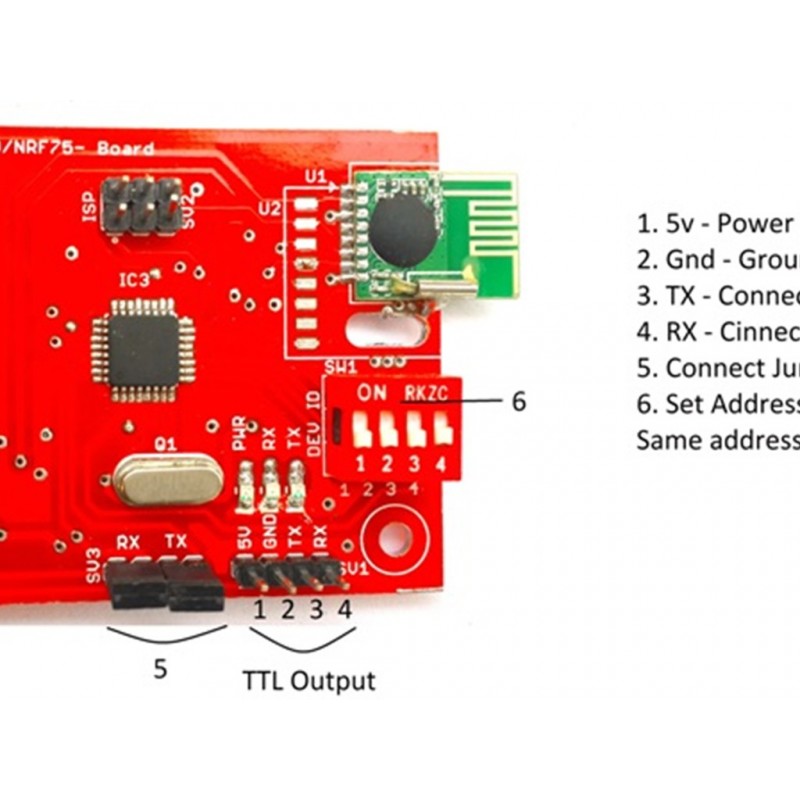
CONNECTION DIAGRAM FOR RFM75 RS232:
-5v-Power supply
-GND-GROUND PIN
-TX-CONNECT TO RX OF MICROCONTROLLER
-RX-CONNECT TO TX OF MICROCONTROLLER
-SET ADDRESS BIT HERE (BOTH TX, RX MUST IN SAME ADDRESS BIT)
CONNECTION STEPS:
-Connect 5v power supply to RFM75RS232
-When connect the power supply “LED will blink”
-Connect Tx pin of RFM75RS232 to microcontroller Rx pin
-Connect Rx pin of RFM 75RS232 to microcontroller Tx pin
-When data passing through Microcontroller then Rx LED of RFM75RS232 will blink
-Both transmitter and receiver address bit should be in even.
NOTE:
If address bit switches are changed then need to press reset.
APPLICATIONS:
-Wireless PC peripherals
-Wireless gamepads
-Wireless audio
-Remote controls
-Home automation
-Toys
PACKAGE INCLUDES:
1 PCS x Rfm75 Rs232 Rf Transreceiver Can Be Used As Zigbee 2 Way Communiaction Same As Xbee
SAMPLE CODING
/*
The circuit:
* RX is digital pin 10 (connect to TX of other device)
* TX is digital pin 11 (connect to RX of other device)
*/
#include <SoftwareSerial.h>
SoftwareSerial mySerial(10, 11); // RX, TX
void setup()
{
// Open serial communications and wait for port to open:
Serial.begin(9600);
while (!Serial)
{
; // wait for serial port to connect. Needed for native USB port only
}
Serial.println("Goodnight moon!");
// set the data rate for the SoftwareSerial port
mySerial.begin(9600);
mySerial.println("Hello, world?");
}
void loop()
{ // run over and over
if(mySerial.available() // if Data available in RFM
{
Serial.write(mySerial.read()); // then transmits to PC
}
if (Serial.available()) { // if Data available in PC
mySerial.write(Serial.read()); //then transmits to RFM
}
}
 9962060070


